This is a construction project for a “Capacitance Operated Relay” (a.k.a Capacity Operated Relay) from the “Electronic Hobbyists’ Handbook” by Rufus P. Turner, first published in 1958. (Library of Congress Catalog Card No. 57-9010)
(Information obtained from the United States Copyright Office indicates this book is no longer under copyright.)
I have added some notes on the construction of this project after the end of the original piece.
Author: Rufus P. Turner
CONTROL DEVICES
(Chapter 7)
One of the most fascinating aspects of electronics always has been the art of remote control. This is the control of distant devices by means of radio signals. Here is real scientific magic! A closely allied art is that of electronic timing. Operations may be timed very precisely or time intervals measured very closely without any of the common mechanical clockwork devices. Electronics does this job accurately and quietly.
The circuits given in this chapter may be adapted to a variety of remote-control operations such as garage-door opening, model- airplane control, opening and closing distant locks, sounding alarms, and similar applications.
CAPACITANCE OPERATED RELAY
Operation of this type of relay results from the nearness of objects. Approach its antenna and the relay closes. Move away and it opens. The capacitance-operated relay often is used in a store window as a “crowd stopper.” With an antenna disc mounted inside the glass, lights can be made to flash on or an animated exhibit set into motion when a bystander places his hand or finger in front of the disc. The capacitance-operated relay also is used occasionally as an intrusion (burglar) alarm.
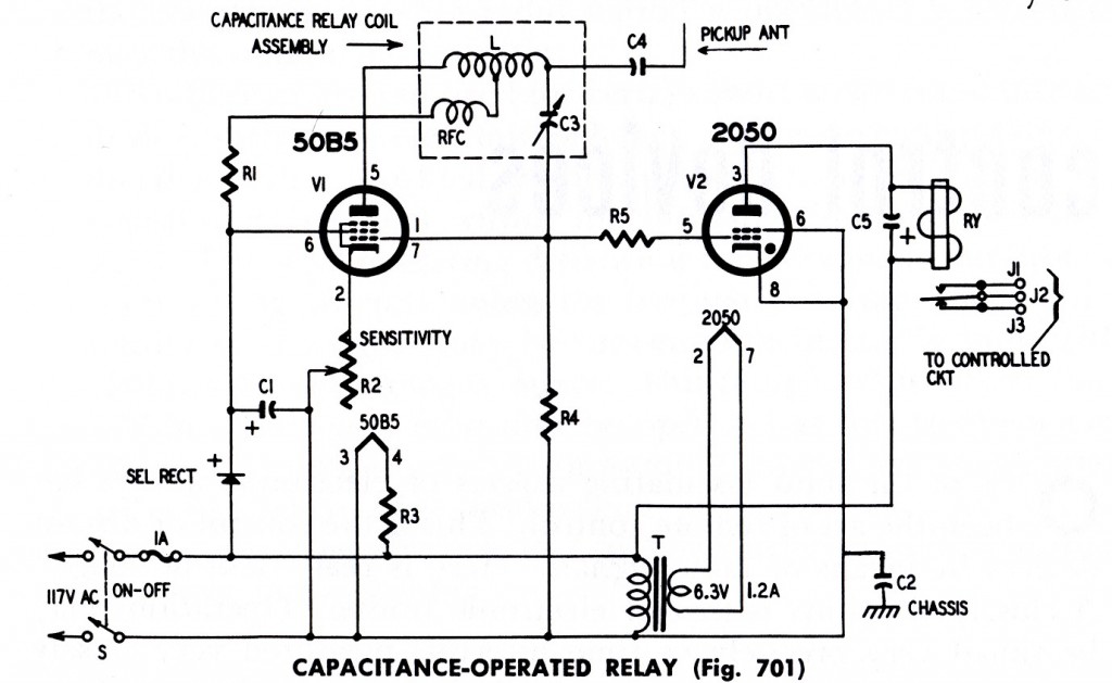
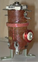
Fig. 701 shows the circuit of a simple capacitance relay. Here, a 50B5 tube is used as an RF oscillator and a 2050 as the relay tube. A manufactured capacitance relay coil assembly (Miller No. 695) includes inductor L, RF choke RFC and trimmer capacitor C3. DC voltage for the plate and screen of the 50B5 is supplied by the selenium rectifier and filter capacitor C1.
A pickup antenna is coupled to the oscillator through capacitor C4. This antenna may consist of a few feet of plain, insulated wire or it may be a metallic disc or plate. In some applications, a wire has been run around a door frame to detect the entry of persons. In another intrusion-detector application, the antenna has consisted of a large metallic plate concealed under a rug in- side a doorway.

Fig. 701. The presence of an object near the antenna will operate the relay. The relay tube is a, thyratron.
(Click picture for larger printable copy.)
———————————————————————————————
PARTS LIST
Resistors:
R1-3,300 ohms, 1 watt
R2-1,000 ohm wire-wound pot
R3-433 ohms, 20 watts (500-ohm adjustable with slider set at 433 ohms)
R4-680,000 ohms
R5-2.2 megohms
Capacitors:
C1-40 uF 150 volt electrolytic
C2, C4-.1 uF 600 volt tubular
C5-10 uF 150 volt electrolytic
Coil: L-capacitance-relay coil assembly Miller No. 695 (C3 and RFC contained in unit)
Transformer: T-6.3-volt 1.2-amp filament (Triad F-14X or equivalent)
Tubes: V1-50B5; V2-2050
SEL-100 ma selenium rectifier
Sockets: octal; 7-pin miniature
Relay: RY-110 volts ac (Advance K1501-S or equivalent)
Miscellaneous:
S-DPST toggle switch
J1, J2, J3-terminal connectors
1-amp fuse
———————————————————————————————
Body capacitance, due to proximity to the antenna, alters the oscillator capacitance and the presence or strength of oscillation. This, in turn, changes the dc bias on the grid of the 2050 gas tube, causing this tube to fire and close the relay. Since the 2050 is ac- operated, it will extinguish and open the relay as soon as the object withdraws and the grid bias shifts back to its original value.
The sensitivity of the circuit depends upon the settings of C3 and R2. If the circuit is too sensitive, it will fall into a hair- trigger type of self-operation. If not sensitive enough, it will respond only to large objects or those in actual contact with the antenna. A compromise must be made between the adjustments of C3 and R2 to give a good combination of sensitivity and reliability.
———————————————————————————————
Additional Editor’s Notes Regarding Construction And Operation
There are several Capacitance Operated Relay circuits that used the Miller No. 695 coil. The circuits that employed a thyratron tube to control the relay seemed to have better performance. Most of these circuits connected the thyratron grid to the grid circuit of the oscillator. When a thyratron tube fires the grid impedance changes due to the ionization of gas within the tube. This lower impedance puts an additional load on the oscillator grid circuit through resistor R5. This additional loading of the oscillator provides hysteresis and gives the device a nice “snap-action” as it is triggered.
The 50B5 oscillator tube can be replaced with a 50C5 which is essentially the same tube, but with an improved basing (pin-out). Simply renumber the pins on the schematic for a 50C5. Also, an octal 50L6GT tube can be used without any other component value changes.
But regardless of the tube chosen there is one modification that should definitely be made. The sensitivity control (R2) controls the bias for the oscillator tube, as well as the gain. This is a tube designed as an audio output tube so it can draw quite a bit of current. In this application the tube does not need to be operated with a very high plate current. A 270 ohm 1 watt resistor should be placed in series with the top of the pot (CCW pin) and the cathode of the tube. This will assure that the bias will never become low enough to cause the tube to draw excessive current. This is really a small design flaw in this circuit, and it was probably the reason a 2 watt wire-wound pot was specified rather than a carbon pot. When this change has been made a 1 watt carbon pot may be used. A carbon pot will also provide better resolution for this critical sensitivity adjustment. The counter-clockwise end of the pot is the upper end, the end connected to the oscillator tube cathode. This is where the slider of the pot would be set for maximum oscillator gain. Note that maximum oscillator gain is the minimum sensitivity for detecting an object.
Another strongly recommended change is to substitute a 1N4007 diode in series with a 100 ohm 1/2 watt resistor for the selenium rectifier. Selenium rectifiers degrade over time and can release toxic gasses if overloaded. Selenium rectifiers are cool to look at, but you’re better off not using them.
Notice that this circuit suggests using an AC relay on direct current, the thyratron tube is a half-wave rectifier. A resistor should be placed in series with this relay. Connect the resistor between the upper end of C5 where it connects to the 2050 plate (pin 3) and the relay coil. Operating an AC relay on DC is possible, but the DC voltage should be significantly lower than the relay’s rated AC voltage. One way to determine a reasonable DC voltage for an AC relay is to apply a variable DC voltage. Increase the voltage until the relay just pulls in and note this voltage, then add about 20% (multiply by 1.2) . Use enough resistance in series with the relay to reduce the DC voltage to this value.
A 110 volt DC relay is a better choice here, but a series resistor may still be needed. Measure the voltage across the relay and add resistance until it is down to 110 volts. Measure the voltage across the resistor to determine how much power will be dissipated. E(squared) divided by R will give you the dissipation wattage. Take this amount and double it to determine what wattage resistor to use.
Resistor R3 is big 20 watt adjustable resistor, but there are ways to eliminate this part. First off, the value of 433 ohms is based upon a line voltage of 115 volts. For a 120 volt line, the resistor should be adjusted to 466 ohms. You can use a 500 ohm 20 watt adjustable resistor as specified, or you can put a 6.8k ohm 2 watt resistor in parallel with a 500 ohm 20 watt fixed resistor to get 466 ohms.
Another way to eliminate this resistor would be to substitute the 6 volt version of the 50B5/50C5 output tube. This tube is a 6CU5, and you merely have to upsize the filament transformer to one with a secondary current rating of 1.8 Amps or better, and connect the 6CU5 filament in parallel with the 2050 filament. The 6CU5 has the same pinout (7CV) as the 50C5 (slightly different from the 50B5).
The capacitor connected from one side of the power line to the chassis is of a fairly high value. If the device is plugged in so that this side of the line is the hot side, the chassis of this unit could deliver a noticeable shock if a person touched it while they were grounded. A three-wire grounding line cord should be used with a circuit like this nowadays, and the neutral (white) wire should be the side connected to C2.
The antenna capacitor, C4 is important for safety, since this device is directly line operated.
The Miller No. 695 coil is very difficult to obtain, and sometimes (albeit rarely) seen in eBay auctions. A future article will discuss how to construct a simple substitute for this coil.
The entire unit can be constructed on an 8″ by 10″ by 2″ deep chassis box. The coil should be located on top of the chassis so it is not close to grounded metal objects. The antenna terminal can be a ceramic standoff placed near to the coil. The connection from the coil to the antenna terminal (via C4) should be kept relatively short.
The adjustment of C3 is not very critical. For small antenna plates of about one square foot or less, loosen the screw a bit until the capacitor plates just begin to separate. A cookie sheet makes a good antenna, but remember to keep it away from any large conducting objects
The adjustment of the sensitivity pot is quite critical. With the unit turned on and warmed up, and an antenna connected, advance the pot clockwise until the relay just pulls in. Then back it off ever so slightly, taking your hand away each time to see if the relay releases. Repeat this process until the relay releases when you move a distance away from the antenna and the unit itself. This process becomes easy to do with a little practice. These units can be set sensitive enough to detect a human hand about a foot away. Things like temperature and humidity changes can affect the adjustment. For a more reliable adjustment, try setting it so that your hand has to be 3 to 4 inches away.
Discuss this article here: http://tubularelectronics.com/Forums/viewforum.php?f=3

