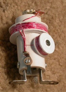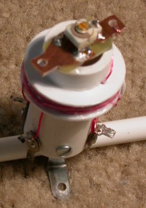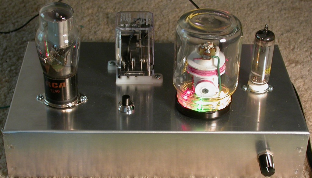
The Capacity Operated Relay is a device that can be used as an electronic switch to activate a variety of things. The novel part of the device is that it is operated by a hand approaching or moving away from an antenna attached to the device without actually touching it. In the middle part of the last Century J. W. Miller Co. designed the Capacity Operated Relay and marketed the Miller Cat #695 Capacity Relay Coil so that the device could be manufactured. These devices were used in animated store window displays such that when a window shopper approached and placed their hand near the antenna it activated the window display. They were also used as burglar alarms. My version of the Capacity Operated Relay will switch 120 Volt appliances (lamps, motors, etc.) on and off when the hand is placed close to the antenna plate. It is a project that has a variety of uses both fun and practical and I learned a lot about electronics and tube systems.
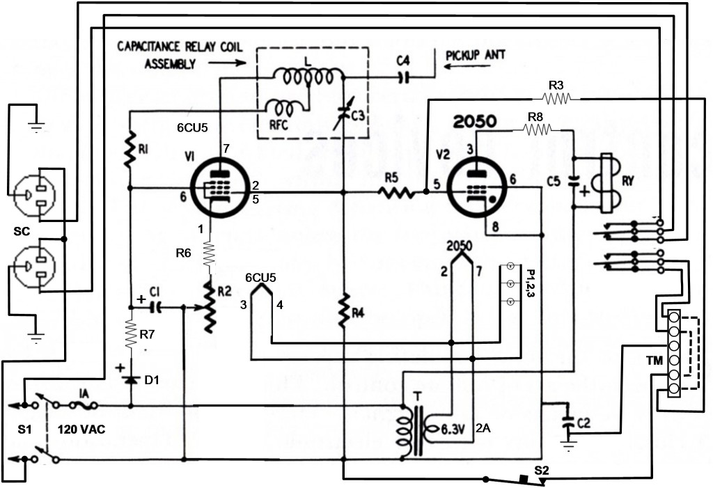
My understanding of how the relay works is that the capacity relay coil causes a 6CU5 tube to oscillate in the RF range. While the tube is oscillating current is drawn through the grid leak resistor (R4). By Ohms Law current going through R4 induces a negative voltage drop across the resistor. This negative voltage is transferred to the grid of the Thyratron tube via resistor (R5) and keeps the Thyratron tube from firing. As the hand approaches the antenna the capacitance between the hand and antenna down loads the oscillator such that oscillation ceases. When this occurs, current flow stops and all the voltage is dropped across the 6CU5 grid and plate and no voltage is dropped across R4, forming an open circuit. Since no voltage is dropped across R4 the grid of the Thyratron trends positive and the tube fires closing the relay.
Schematic
Parts List
- R1 3.3 KΩ 1 Watt
- R2 1 KΩ 1 Watt Pot
- R3, R4 680 K Ω ½ Watt
- R5 2.2 MΩ ½ Watt
- R6 270 Ω 1 Watt
- R7 100 Ω ½ Watt
- R8 560 Ω ½ Watt
- C1 40 µF 150 Volt Electrolytic
- C2, C4 .1 µF 600 Volt Mylar
- C3 3.5 – 40 pF 100 Volt Trimmer Capacitor – Mouser # 659-GYC40000
- C5 10 µF 150 Volt Electrolytic
- L 125 µh Oscillator Coil
- RFC 1mh RF Choke
- V1 6CU5
- V2 2050
- T 6.3 Volt 2A Filament Transformer
- S1 DPST 120 Volt On Off Switch
- S2 SPST Normal Closed Momentary Switch – Mouser # 506-MSPF101B
- RY 110 Volt DC DPDT Relay – Mouser # 655-27E043
- Relay Socket Mouser # 655-KUEP-11D15-110
- TM 6 Lug Screw Terminal – Mouser # 534-4192
- 4 – Five Solder Lug Barrier Terminal Strip
- 7 Pin Mini Tube Socket
- 8 Pin Octal Tube Socket
- SC Dual Utility Outlet 120 Volt
- 1 Amp Fuse and Fuse Holder
- P1,2,3 6 V Lamps – Radio Shack # 272-1098
- Aluminum Chassis Box & Cover (10” X 6” X 2”) – Antique Elec. Supply # PH-1444-16 & PH-1434-16
- Knob for R2
- 24 Gauge Magnet Wire
- 32 Gauge Magnet Wire
- Three Wire power cord with three prong plug
- ½” PVC Pipe
- ¼” Plastic Tube
- Sheet Plastic (for coil retaining rings)
- Grommets for power cord and antenna
- Hook Up Wire
- Coil Dope
- Small Jar to cover Capacity Relay Coil Assembly
- Hardware parts constructed from scrap metal
- 5 Min Epoxy Glue
Capacity Relay Coil Assembly
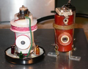
Comparison of a vintage Miller #695 Capacity Relay Coil to my copy
The Capacity Relay Coil is the heart of the capacity relay device. These coil assemblies were manufactured by J. W. Miller Co. (Cat # 695) for many years but are no longer available except from collectors. I planned to build a Theremin from an old Popular Electronics magazine design that called for the use of the Miller 695 Coil. But, given the difficulty of obtaining the coil assembly I decided to have a go at building one from scratch. After all how hard could it be? I decided that if I was going to do this that it would be a good idea to build the Capacity Relay device first to see if my home made coil assembly would work rather than try it out in the more complex Theremin. With a lot of help from on line friends (Izzy Weird in particular) I obtained an estimate for the coil component specs and proceeded with the build. The coil assembly consists of three parts:
1.) 125 μh Oscillator Coil (L on schematic)
2.) 1 mh RF Choke (RFC on schematic)
3.) 3.5 pf – 40 pf Trimmer Capacitor (C3 on schematic)
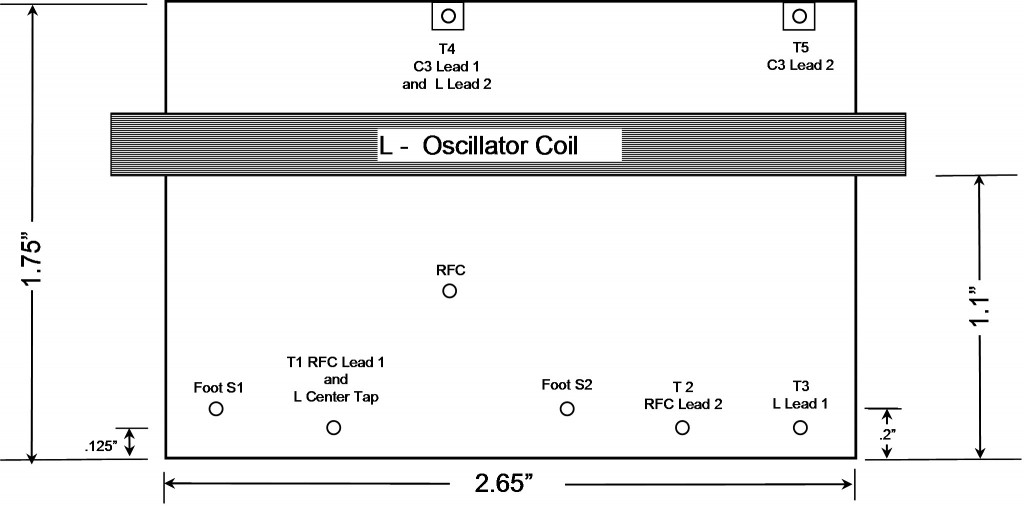
The coil assembly core is constructed from a short segment of ½” PVC irrigation pipe available from your local hard ware dealer. The pipe is cut to length and holes drilled per the template shown below.
Template for Capacity Relay Coil Assembly Core
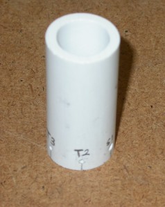
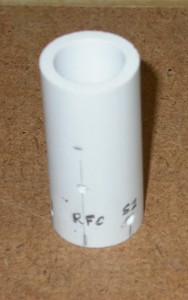
The coil assembly cores cut to size and holes drilled for the components.
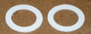
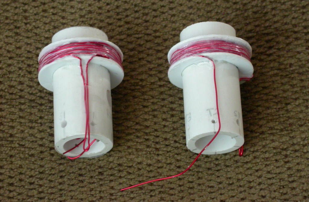
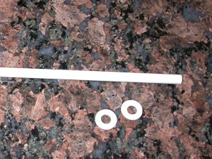
The oscillator coil retaining rings and the RFC coil retaining rings are cut from sheet plastic available from your local art or hobby store. The oscillator coil retaining ring has a radius of .625” and the RFC coil retaining ring has a radius of .34”. I used a compass to draw the inside and outside diameters of the retaining rings on the plastic then cut out with scissors. The retaining rings should fit snuggly over the coil cores.
The oscillator coil consists of 68 (8 X 8 + 4) winds of 24 gauge magnet wire. I first glued the lower retaining ring onto the core assembly then made 8 winds. I then pushed the upper retaining ring down onto the winds and glued in place. I continued to wind the coil until 34 winds had been completed then took the wire down to T1 for the center tap. I finished the rest of the winds then sealed the coil with coil dope. Be sure to leave enough lead wire to attach to the terminal posts. The number of winds for both the oscillator and the RFC were determined from coil winding formulas found on line. Wikipedia has an excellent summary of coil winding.
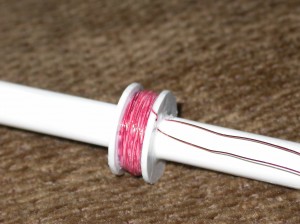
The RFC coil is constructed similar to the oscillator coil. I used 8 mm (.315”) plastic tube available from your local hobby store as the core. The choke is wound with 324 (18 X18) winds of 32 gauge magnet wire. I first glued a retaining ring on the tube then wound the first 18 winds. I slipped on the other retaining ring and glued it in place. I finished winding the coil and secured with coil dope. When dry the tubing is cut off and the coil is attached to the assembly core with a wood screw.
–
–
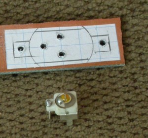
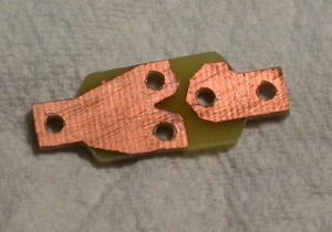
For the trimmer capacitor I drilled, cut out then etched a small piece of PC board leaving enough overhang to provide for the terminals T4 & T5 (see core template).
–
–
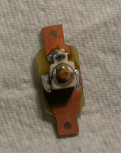
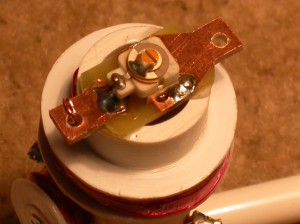
The trimmer capacitor is soldered to the PC board which was then glued to the coil core. Note that the vintage trimmer caps shown in the photos were replaced in the final build with modern trimmer caps because the old caps were leaky and did not work well.
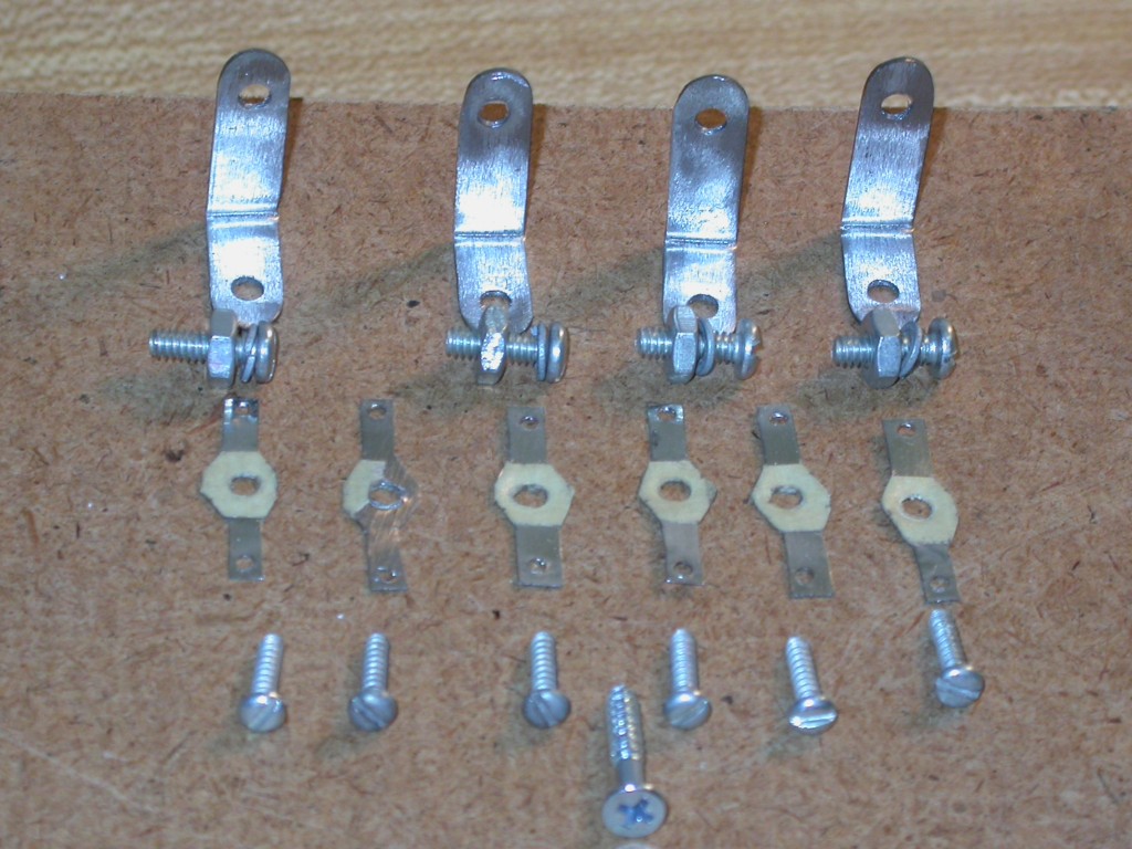
The solder terminals and feet for the coil assembly were made from scrap steel I had laying around and attached using steel screws, bolts, nuts and washers. Commercial soldering lugs would work just as well.
After the hardware, RFC and trimmer cap are attached to the core the assembly is soldered up using the schematic and core template as a guide. The solder terminals are insulated from the core plastic by small pieces of card stock that I punched out from the backing on a stationary tablet using a paper punch. This prevents heat from melting the core material when the lugs are soldered up. This completes the capacity relay coil assembly.
Chassis Construction
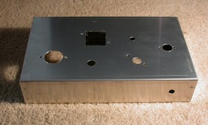
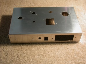
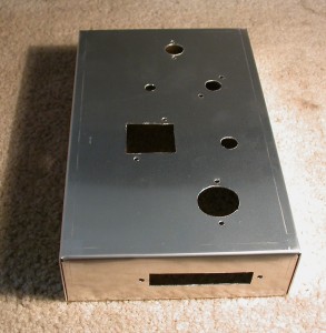
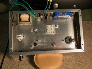
Holes are cut in the chassis box to fit the various components. These include the tube sockets, relay socket, outlet, terminal strip, power switch, lockout switch, antenna, capacity relay coil, power cord, potentiometer and transformer.
–
–
–
–
Chassis Component Mounting
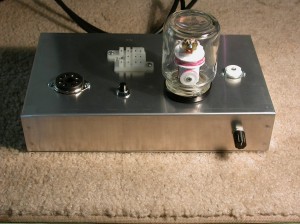
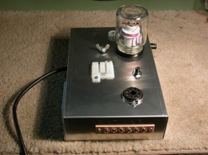
The components are mounted as shown. I mounted the capacity relay coil on the surface and inside a small jar because I wanted to show off the coil assembly. The jar prevents the user from being shocked by the exposed coil leads. Un-screw the jar from its lid and remove it to expose the coil to adjust the trimmer capacitor.
Wiring the Components
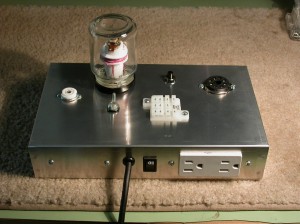
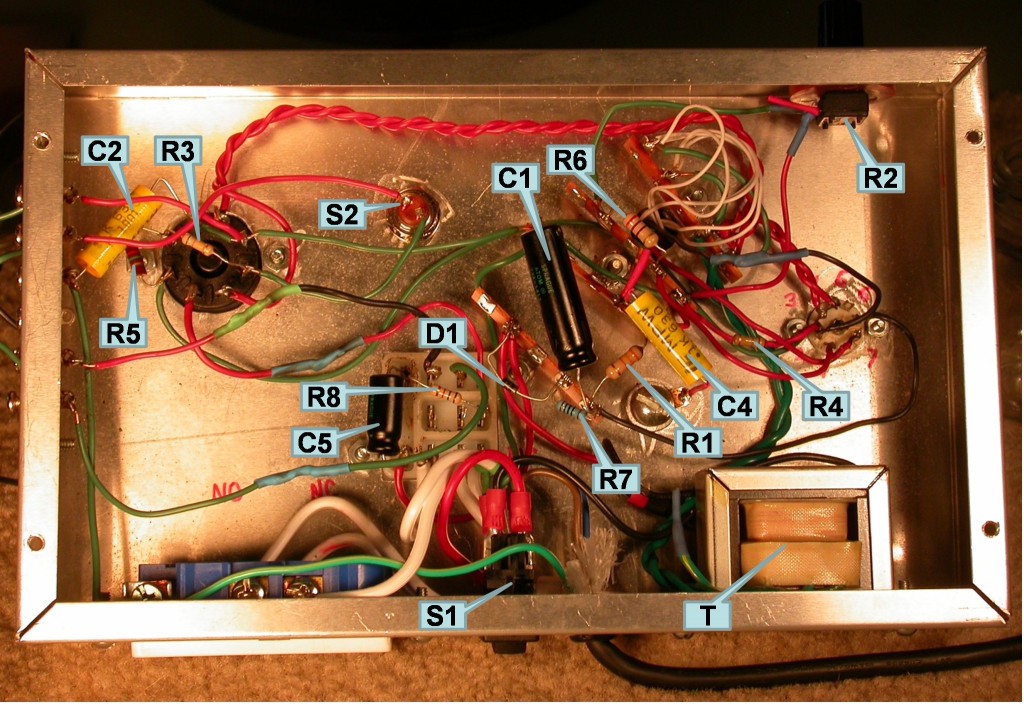
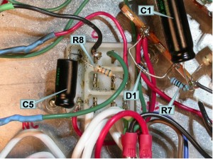
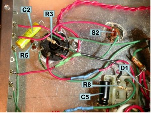
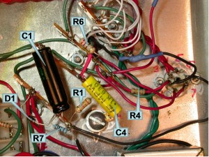
Using the schematic as a guide I wired up all the components. The figures below show the result. I used four 5 pin solder lugs as attachment points for the resistors, capacitors connecting wires etc. The NC (no connection) pins on the octal socket and the relay socket were also used when convenient. The solder lugs were attached to the chassis using the nuts and bolts used to attach the coil assembly and the relay socket. Do not use the center pin on the solder lugs because they are grounded to the chassis. The tube heater elements were wired using twisted pairs of wires. Notice on the schematic that the outlet sockets by pass the power switch. Be sure to remove the connecting bus on the hot side of the sockets such that when wired up, one is in the normal on position and one is in the normal off. Be sure and ground the chassis using the green grounding wire on the power cord. I used a nut, bolt and grommet with washers to pass the antenna lead through the chassis. Be sure to insulate the antenna lead from the chassis. Although I did not do so the antenna lead should be placed as far from the other components as possible. Placing it too close make sensitivity adjustment more difficult. It has be recommended to even remove the antenna circuit from the chassis entirely.
–
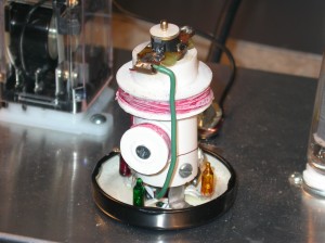
The lamps are glued to the jar lid before it is attached to the chassis. Note the new trimmer capacitor on top of the coil assembly.
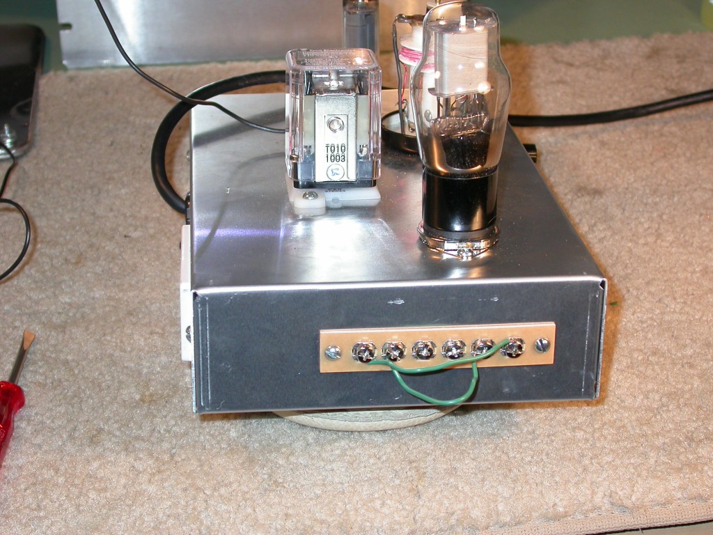
In this picture the terminal strip is wired to kick in the lock out switch (the dashed lines on the schematic). In this configuration when the relay is activated it will stay closed until the lock out switch (S2) is pushed. When these wires are removed the relay turns on and off when the hand approaches and withdraws from the antenna plate.
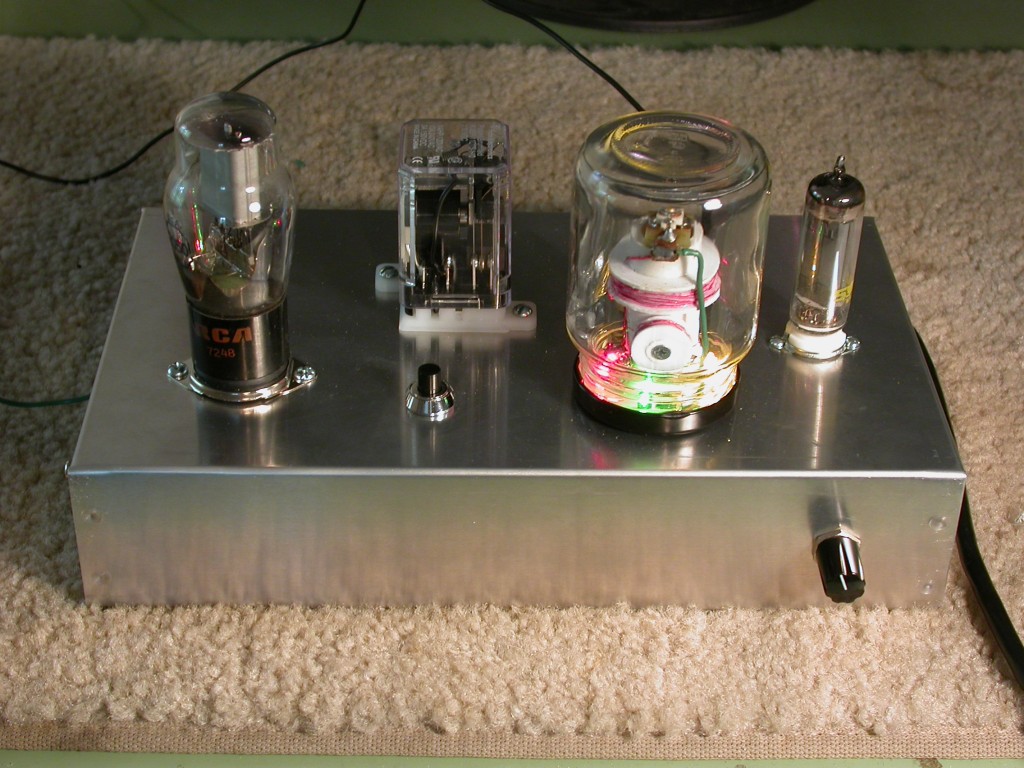
The Capacity Operated Relay turned on. The lights were added just for fun.
A Couple of Last Notes
Although my relay works great I noticed that I have nearly the maximum capacitance dialed in on the C3 trimmer capacitor. At any other setting the Thyratron tube fires and the relay closes and stays that way The trimmer capacitor has a range of 3.5 pf – 40 pf.. There are three possible reasons for this:
1.) The trimmer should have a higher rating (20 pf -60 pf).
2.) The antenna circuit is to close to the other components.
3.) The coils I wound are not at the correct specs.
I plan to conduct a few experiments with different trimmers, antenna locations and make more coil assemblies.
For more information on how a capacity relay works, see the following:
Electronics Hobbyists Hand Book – Rufus P. Turner
Electronics Made Easy – Lothar Stern
Tubular Electronics: “Build A Capacitance Operated Relay” by Izzy Weird
Please Visit The Article Forum:
- R1 3.3 KΩ 1 Watt
- R2 1 KΩ 1 Watt Pot
- R3, R4 680 K Ω ½ Watt
- R5 2.2 MΩ ½ Watt
- R6 270 Ω 1 Watt
- R7 100 Ω ½ Watt
- R8 560 Ω ½ Watt
- C1 40 µF 150 Volt Electrolytic
- C2, C4 .1 µF 600 Volt Mylar
- C3 3.5 – 40 pF 100 Volt Trimmer Capacitor – Mouser # 659-GYC40000
- C5 10 µF 150 Volt Electrolytic
- L 125 µh Oscillator Coil
- RFC 1mh RF Choke
- V1 6CU5
- V2 2050
- T 6.3 Volt 2A Filament Transformer
- S1 DPST 120 Volt On Off Switch
- S2 SPST Normal Closed Momentary Switch – Mouser # 506-MSPF101B
- RY 110 Volt DC DPDT Relay – Mouser # 655-27E043
- Relay Socket Mouser # 655-KUEP-11D15-110
- TM 6 Lug Screw Terminal – Mouser # 534-4192
- 4 – Five Solder Lug Barrier Terminal Strip
- 7 Pin Mini Tube Socket
- 8 Pin Octal Tube Socket
- SC Dual Utility Outlet 120 Volt
- 1 Amp Fuse and Fuse Holder
- P1,2,3 6 V Lamps – Radio Shack # 272-1098
- Aluminum Chassis Box & Cover (10” X 6” X 2”) – Antique Elec. Supply # PH-1444-16 & PH-1434-16
- Knob for R2
- 24 Gauge Magnet Wire
- 32 Gauge Magnet Wire
- Three Wire power cord with three prong plug
- ½” PVC Pipe
- ¼” Plastic Tube
- Sheet Plastic (for coil retaining rings)
- Grommets for power cord and antenna
- Hook Up Wire
- Coil Dope
- Small Jar to cover Capacity Relay Coil Assembly
- Hardware parts constructed from scrap metal
- 5 Min Epoxy Glue
